Physical controls / Interface software / Operator research
Designing controls
for a new propulsion system.
Dynafin’s blades are controlled individually. I explored a simpler request from the person at the controls: a direction and an amount of thrust.
For my master’s thesis, I built two physical levers connected to screen interfaces. Operator feedback and the constraints of the build changed the design.
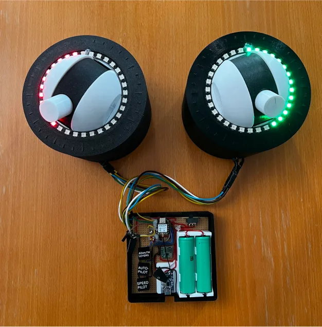
My workResearch, interaction modelling, lever prototypes, electronics and interface software. ABB developed the propulsion system.
ScopeA research prototype evaluated in a simulated setting. Final interface screens remain confidential.
Published thesis ↗The machine / Why it needs a translator
One request,
many moving blades.
Dynafin’s main wheel turns and carries vertical blades. Each blade’s angle keeps changing as it goes round, so several blades are always moving through the water on different paths.
That is what makes the controls hard. The person steering asks for a direction and an amount of thrust; the system has to turn that request into wheel speed and blade motion. The thesis distinguishes two kinds of blade path, below and above an eccentricity of 1. Dynafin reaches the trochoidal kind, a wave like a fish’s tail, with several blades.
Cyclorotor principles and Dynafin’s trochoidal motion: public thesis §2.5, p. 14.
One blade’s path, above 1
Advance ratio 1.5: the wheel moves forward faster than the blade swings back, so the loops open into a wave, like a fish’s tail. This is the shape the thesis calls trochoidal.
Explore the blade motion
These drawings vary one quantity, the advance ratio: how fast the wheel moves forward compared with how fast a blade swings round it. Below 1 the blade loops back on its path; above 1 the loops open into a wave. Those are the two shapes in the thesis’s Fig. 2.2. The drawings do not model the blades’ axis offset, which the thesis calls eccentricity, or ABB’s blade control.
Below 1
Advance ratio 0.6: the wheel moves forward more slowly than the blade swings round, so the blade loops back on its path. This is the shape the thesis calls epicycloidal.
At 1
Advance ratio 1.0: the two speeds match, and the loop closes into a sharp point.
The interface / A tradeoff identified in evaluation
How much can
one arrow explain?
The prototype summarised the two stern propulsors as one arrow from the centre of a dial: its direction showed the thrust angle, its length the total thrust. The arrow was added after operator feedback.
An even split
50 % from port, 50 % from starboard. The combined arrow points straight ahead at full length. The pushes balance: no turning effect.
An uneven split
75 % from port, 25 % from starboard. The combined arrow points straight ahead at full length. The pushes no longer balance, so they also create a turning tendency: the bow tends to swing to starboard.
An arrow like this is the resultant force. It cannot show torque, the turning effect, because that depends on where each push acts. In the evaluation I described the choice as a balance between enough information for decisions and a display that stays clear. The thesis reports that the simplified arrow matched operators’ expectations, and leaves the right level of detail to further evaluation.
Finding: public thesis §6.3.3, pp. 56–57. The arrow’s origin in operator feedback: §7.2.4, p. 65. Two stern propulsors without a bow thruster: the thesis scenario, p. 41.
The same two stern propulsors. A shaded wedge from the port propulsor covers the directions in which its jet of water reaches the starboard propulsor.
Two propulsors can also wash each other.
Aiming one propulsor’s jet at the other is usually avoided, because it risks cavitation. Operators of existing cyclorotors also reported doing it on purpose, to wash debris out of the other propulsor.
So the zone is not simply forbidden, and on the new system it might depend on speed. I concluded that potential interference between the propulsors is worth showing on the interface.
Public thesis pp. 33–34 and 64.
What changed / The build
The ring didn’t fit.
A component choice became a packaging problem.
Changing the ring also meant changing the lever.
Size constraints forced a change from the planned 60-LED ring to 32 LEDs, along with a redesign of the internal electronics and changes to the lever’s scale.
Thesis §5.2.3, p. 47.
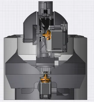
The housing was only one part of the build. Early homemade Hall sensors were too imprecise for the angle readout, so the angles came from feedback servos instead. Microcontroller integration then limited what those motors could do.
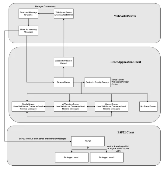
I modelled and printed the levers, built the electronics, and connected the ESP32 client to React interfaces through a WebSocket server.
Inspect the software connections
+135°: 12 of 32 LEDs lit from LED 0 clockwise, 12 green and 0 red.
The ring, as my code drove it
Each lever read its angles from 360° feedback servos. The ESP32 lit the 32-LED ring in proportion to the turn, about one LED for every 11°. LEDs 0–15 were green and 16–31 red, so a positive turn filled green first; a turn the other way filled from LED 31, red first.
The loop paused 50 ms after each pass. When any of the four angles, two per lever, had moved more than 5° since it was last sent, all four went to the WebSocket server; smaller movements sent nothing.
A message the prototype would send (one of four)
{"command": "currentOrientation1", "orientation1": 135}This page sends nothing. Turn the lever to see when the prototype would have sent.
What the assembled rig made possible
The physical levers and screen interfaces shared a WebSocket server. This connected a hand-operated prototype to the interface concept that operators could try.
- Physical lever
- ESP32 client
- WebSocket server
- React interfaces
Simplified from the published architecture, Fig. A.5, p. 89. It shows connections, not timing.
What changed / The display
The controls changed
after expert feedback.
Feedback from maritime experts led me to reposition the angle labels: 0° at the bottom, 180° at the top.
This was a correction to how direction was represented. The display needed to follow the forward-navigation convention used by its operators.
The command-post panel changed too: I added dedicated mode buttons. Blinking feedback was slowed so changes could be seen.
Documented revisions: thesis §5.3, pp. 47–48.
Why the modes mattered
Operators and experts asked for clear mode indicators and dedicated buttons to switch modes. Experts also recommended adding new functions as sub-modes rather than more complexity in the main interface, with a prominent indicator for higher-power modes.
Public thesis pp. 31, 53–54.
Inspect the proposed mode structure
- Maneuvering mode, at slow and high speeds. Sub-mode: high-power mode. Leads to the crash stop.
- Sea mode, at high speeds. Sub-modes: additional modes and sea-mode features, and further additional modes. Leads to the crash stop.
- Crash stop, the common fail-safe.
A diagram in three rows. Middle row: maneuvering mode, spanning slow and high speeds, and sea mode at high speeds. Top row: sub-modes. A high-power mode connects to maneuvering mode; additional modes and sea-mode features connect to sea mode; further additional modes connect to sea mode as well. Bottom row: both main modes lead to a crash stop.
A command and a response
are different information.
A snapshot half a second after a request for 80 %, starting from 0 %. The set line moved at once; the simulated response is still on its way.
The prototype could register an input immediately. The system’s movement toward that request was simulated. Keeping those states distinct became a central feedback concern.
Where that simulation stopped →Who informed these changes?
The research involved five current or former operators, including two maritime instructors. Three operators with cyclorotor experience contributed story interviews. A workshop brought a captain together with engineering, management and design.
Research and implementation: thesis pp. 30–50 ↗What remains / The response
A rig operators
could try.
Four operators evaluated the prototype—three in person and one remotely. They tried the implemented interactions and discussed functions that were still conceptual.
How vessel response changes the feedback problem
Feedback that suits one vessel can be inadequate on another. On small vessels the response is easy to feel and the window view gives a reference; on large ones the lag is longer and operators rely on instruments. The prototype scenario, super-yachts, passenger ferries and small cruise ships, sat between.
Show the full vessel scale
- Tugboats
- Super-yachts
- Passenger ferries
- Small cruise ships
- Large ferries
- Large cruise ships
Smaller vesselsThe response is easy to feel, with little lag, and the window view gives a reference.
The prototype scenarioSuper-yachts, passenger ferries and small cruise ships: a middle ground.
Larger vesselsMore lag and inertia, more reliance on instruments, and more confirmation while the operator waits for movement.
What the work established
A physical test rig, connected screens, and documented design revisions following operator feedback.
The evaluation exposed unresolved questions about modes and how to communicate the system’s response.
What it could not establish
Safe operation or performance on a vessel. Feedback was largely simulated, including a simplified one-second response.
Some modes and feedback mechanisms were incomplete. The combined arrow left out torque, as shown above. Participants sometimes disagreed.
Evaluation and limitations: thesis pp. 51–59.
Based on my public master’s thesis, Enhancing Maritime Navigation, 30 September 2024. Original artifacts come from the public thesis and portfolio; drawings made for this page are identified in their captions.
Read the thesis ↗Back to the photographs →